Build a 4WD autonomous car with Arduino
Arduino Uno tutorials
🕑 This lesson will take about 45 minutes
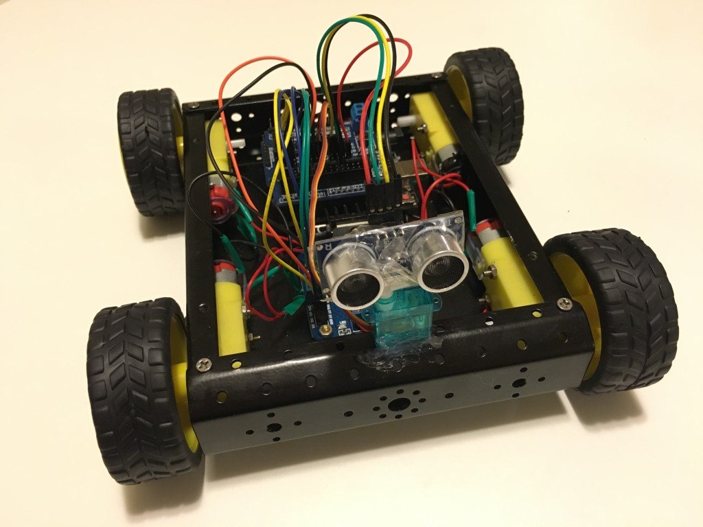
In this lesson, you will learn to make a 4WD car with obstacle avoidance. This project involves building a 4WD car with an Arduino and ultrasonic sensor that can detect nearby objects and change its direction to avoid these objects. You can also extend this project with a servo motor that sweeps the ultrasonic sensor left and right for greater “vision” of obstacles surrounding the car.
You can extend this project by adding more sensors such as ultrasonic sensor to the rear so that the car doesn’t reverse into objects, speed detection sensors to measure speed, line following sensors, and LED brake lights and headlights. You could even add light sensors and LEDs to turn headlights on in low-light conditions or a Bluetooth module to control the car remotely using a smartphone app.
Parts required
Here is what you will need:
1 x Arduino Uno board
1 x 4WD Robotic Car kit (4 wheels, 4 DC motors, chassis, AA battery holder, screws)
6 x AA batteries
1 x 9V battery
1 x 9V battery power cable barrel jack connector
1 x L298N Motor Module
1 x Arduino Sensor Shield v5.0
1 x HC-SR04 Ultrasonic Sensor
Wires:
4 x female-to-female jumper wires for Ultrasonic Sensor
8 x female-to-female jumper wires for the Motor Module to Sensor Shield
8 x bare-ended wires to go from the four motors to the Motor Module
2 x bare-ended wires to go from the Motor Module to Sensor Shield
Arduino IDE software (free download at http://www.arduino.cc)
1x USB cable (A male plug to B male plug)
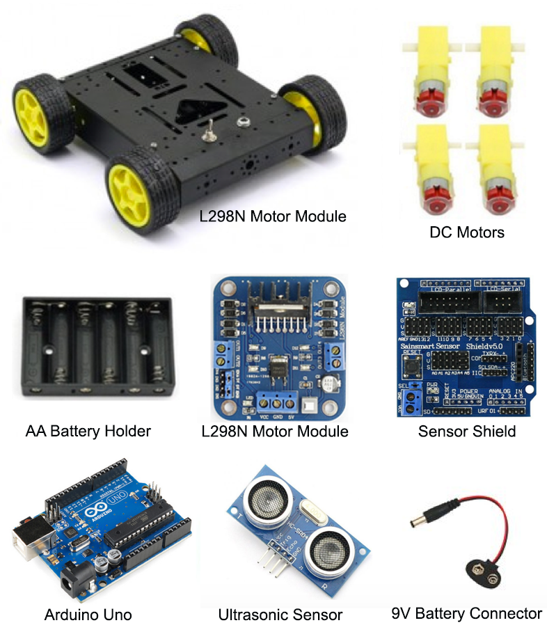
Below are images of the main components you need (apart from the wiring and batteries) – the different car parts, shields, modules and sensors.
Assembling the car
The first thing to do is to assemble the car frame and attach the motors to the wheels. Once the car is assembled, you’ll need to wire up the different components. Follow these instructions and refer to the schematic below to connect the different components in the car.
Connect the red wire (voltage) from the AA battery enclosure to VCC on the L298N Motor Module.
Connect the black wire (ground) from the AA battery enclosure to GND on the L298N Motor Module.
Connect the red wire from Motor A1 (rear left) and the red wire from Motor A2 (front left) to OUT1 on the Motor Module (both wires can be twisted together and will go into OUT1 – the schematic further down this page shows how to do this).
Connect the black wire from Motor A1 (rear left) and the black wire from Motor A2 (front left) to OUT2 on the Motor Module.
Connect the red wire from Motor B1 (rear right) and the red wire from Motor B2 (front right) to OUT3 on the Motor Module.
Connect the black wire from Motor B1 (rear right) and the black wire from Motor B2 (front right) to OUT4 on the Motor Module.
Connect a female-to-female jumper wire from ENA (Engine A) on the Motor Module to signal (S) pin 1 on the Sensor Shield (the #2 pin in the S row. There are three rows – S stands for Signal, V for Voltage and G for Ground).
Connect a female-to-female jumper wire from 5V (next to ENA) on the Motor Module to voltage (V) pin 1 on the Sensor Shield (it doesn’t really matter which pin for voltage as long as it is in the V row).
Connect a female-to-female jumper wire from IN1 on the Motor Module to signal pin 2 on the Sensor Shield.
Connect a female-to-female jumper wire from IN2 on the Motor Module to signal pin 3 on the Sensor Shield.
Connect a female-to-female jumper wire from IN3 on the Motor Module to signal pin 4 on the Sensor Shield.
Connect a female-to-female jumper wire from IN4 on the Motor Module to signal pin 5 on the Sensor Shield.
Connect a female-to-female jumper wire from 5V (next to ENB) on the Motor Module to voltage (V) pin 6 on the Sensor Shield (it doesn’t really matter which pin for voltage as long as it is in the V row).
Connect a female-to-female end wire from ENB (Engine B) on the Motor Module to signal (S) pin 6 on the Sensor Shield.
Attach the Ultrasonic Sensor to the front of the car with the sensor pointing forward to detect objects in front of the car. You can use a hot glue gun, tape, blu-tack, or a 3D printed/laser cut mount to attach the sensor and ensure it is firmly mounted. Make sure it is not too close to the ground as the sensor might accidentally detect the ground as an object to avoid.
Use female-to-female jumper wires to connect the Ultrasonic sensor to the Sensor Shield. Firstly, attach the TRIG pin from the Ultrasonic sensor to signal (S) pin 8 on the Sensor Shield. Attach the ECHO pin from the ultrasonic sensor to signal (S) pin 9 on the Sensor Shield. Attach the VCC pin from the Ultrasonic Sensor to the voltage (V) pin 10 on the Sensor Shield. Lastly, attach the GND pin from the Ultrasonic Sensor to the GND (G) pin 11 on the Sensor Shield.
Now stack the Sensor Shield on top of the Arduino Uno board making sure not bend or damage any pins when they are inserted into the Arduino pin slots. Connect a 9V Battery Barrel Jack Connector to a 9V battery and then plug this into the Arduino’s power port (see diagram below).
That’s it! Now all you need is batteries and to upload the code!
Please note: There are several variations of the sensors and modules and several different ways to wire this up. For example, you can add a charging component to charge batteries and you can also add different switches. There may be other better methods to use, but I have gone for the simplest way I know of to set this up.

The code
Here is the code to get your robot moving. Upload the following code to your Arduino using the Arduino IDE software. This code will make the car go forward and move around obstacles detected by the ultrasonic sensor. You can modify this code to use more sensors or to be remotely controlled using a smartphone app connected to the Arduino via Bluetooth.
Remote control with Bluetooth
Rather than using an ultrasonic sensor to make the car autonomous, you can use a Bluetooth module to remotely control the car wirelessly using a smartphone. You can modify this code to receive string commands from an app via a Bluetooth connection - use the Serial Monitor to check which commands are received and modify the code so that, for example, when a “forward” command is received the car will drive forward. There are a few apps available on the iOS App Store and Google Play Store for controlling an Arduino car via Bluetooth. You can download the LearnThruTech RC CarController App to connect to the Bluetooth module and send string commands to the Arduino to make the car go forward, back, left or right. Try it out!