Build a 2WD robotic car with Arduino
Arduino Uno tutorials
🕑 This lesson will take about 20 minutes
In this lesson, you will learn how to use an Arduino to build a 2WD robotic car. You can extend this project by using ultrasonic sensors to detect and avoid obstacles, line sensors to follow a path, or sensors to measure wheel speed (for improved accuracy when steering or maintaining a straight line).
Required parts
Here is what you will need:
1 x Arduino Uno board
1 x 2WD robotic car kit (2 wheels, 2 motors, and a chassis)
4 x AA batteries
1 x L298P Shield R3 DC Motor shield
6 x wires to connect motors and batteries to the motor shield (2 wires should be soldered to each motor)
Arduino IDE software (free at http://www.arduino.cc)
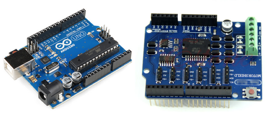
The three images below show the 2WD car kit before assembly, the Arduino Uno board, the L298P motor shield, and the assembled car.


Assembling the car kit
Assemble all chassis parts, solder two wires to the DC motors, and attach the motors to the wheels (if not already assembled).
Stack the Motor Shield on top of the Arduino Uno carefully, ensuring the pins match up in their correct position and don’t get bent or damaged.
Insert the red wire from the battery enclosure into the VIN slot on the Motor Shield. Use a small screwdriver to clamp the wire into the slot.
Insert the black wire from the battery enclosure into the GND slot on the Motor Shield. Use a small screwdriver to clamp the wire into the slot.
Insert the red wire from Motor A to the A+ slot on the Motor Shield, and the black wire from Motor A to the A- slot on the Motor Shield. Use a small screwdriver to clamp the wires into their slots.
Connect the red wire from Motor B to the B+ slot on the Motor Shield, and the black wire from Motor B to the B- slot on the Motor Shield. Use a small screwdriver to clamp the wires into their slots.
Connect the Arduino Uno board to the computer via the USB cable and upload the code below using the Arduino IDE software.
Insert four AA batteries in the battery enclosure and watch your car go!
If your robot goes in the wrong direction or doesn’t move, check that you have the Motor pins in the correct places and make sure no pins are loose.
Extra challenges
Control your robotic car using an Android app on a smartphone via Bluetooth (refer to the Controlling an LED with a Bluetooth-connected smartphone lesson for instructions on how to receive Bluetooth commands from a smartphone to control an Arduino (use the code at the bottom of that lesson page and modify it to receive string commands like “forward”, “backward”, “left”, and “right” to control the car. You can use a free app like the LearnThruTech RC CarController app on the iOS App Store to control the car remotely.
Use line sensors to make the car follow a path or ultrasonic sensors to make the car autonomously avoid obstacles. You can also add speed sensors to control the speed of both motors so that the car can drive straight without veering off in one direction.
The code
Use the following code to test that your wheels spin and that your robot is wired up correctly. Modify the code to make the robot drive in a particular pattern.